By: Team W10-3 Since: Feb 2019 Licence: MIT
1. Introduction
Welcome to the Developer Guide for Equipment Manager!
Equipment Manager is an application that allows engineers to keep track of the Preventive Maintenance schedule of all Resuscitation Devices in Singapore. It will help engineers plan the number of equipment to carry out preventive maintenance, and also keep track on each equipment details such as status and location.
Objectives of the application include:
-
Providing commands such as search and filter to search and filter equipment serial number, equipment status or work list respectively.
-
Displaying location of equipment in Google Maps.
-
Planning the most efficient route to take for visiting multiple locations.
2. Setting up
2.1. Prerequisites
-
JDK
9or laterJDK 10on Windows will fail to run tests in headless mode due to a JavaFX bug. Windows developers are highly recommended to use JDK9. -
IntelliJ IDE
IntelliJ by default has Gradle and JavaFx plugins installed.
Do not disable them. If you have disabled them, go toFile>Settings>Pluginsto re-enable them.
2.2. Setting up the project in your computer
-
Fork this repo, and clone the fork to your computer
-
Open IntelliJ (if you are not in the welcome screen, click
File>Close Projectto close the existing project dialog first) -
Set up the correct JDK version for Gradle
-
Click
Configure>Project Defaults>Project Structure -
Click
New…and find the directory of the JDK
-
-
Click
Import Project -
Locate the
build.gradlefile and select it. ClickOK -
Click
Open as Project -
Click
OKto accept the default settings -
Open a console and run the command
gradlew processResources(Mac/Linux:./gradlew processResources). It should finish with theBUILD SUCCESSFULmessage.
This will generate all resources required by the application and tests. -
Open
MainWindow.javaand check for any code errors-
Due to an ongoing issue with some of the newer versions of IntelliJ, code errors may be detected even if the project can be built and run successfully
-
To resolve this, place your cursor over any of the code section highlighted in red. Press ALT+ENTER, and select
Add '--add-modules=…' to module compiler optionsfor each error
-
-
Repeat this for the test folder as well (e.g. check
HelpWindowTest.javafor code errors, and if so, resolve it the same way)
2.3. Verifying the setup
-
Run the
seedu.equipment.MainAppand try a few commands -
Run the tests to ensure they all pass.
2.4. Configurations to do before writing code
2.4.1. Configuring the coding style
This project follows oss-generic coding standards. IntelliJ’s default style is mostly compliant with ours but it uses a different import order from ours. To rectify,
-
Go to
File>Settings…(Windows/Linux), orIntelliJ IDEA>Preferences…(macOS) -
Select
Editor>Code Style>Java -
Click on the
Importstab to set the order-
For
Class count to use import with '*'andNames count to use static import with '*': Set to999to prevent IntelliJ from contracting the import statements -
For
Import Layout: The order isimport static all other imports,import java.*,import javax.*,import org.*,import com.*,import all other imports. Add a<blank line>between eachimport
-
Optionally, you can follow the UsingCheckstyle.adoc document to configure Intellij to check style-compliance as you write code.
2.4.2. Updating documentation to match your fork
After forking the repo, the documentation will still have the SE-EDU branding and refer to the nus-cs2103-AY1819S2/addressbook-level4 repo.
If you plan to develop this fork as a separate product (i.e. instead of contributing to nus-cs2103-AY1819S2/addressbook-level4), you should do the following:
-
Configure the site-wide documentation settings in
build.gradle, such as thesite-name, to suit your own project. -
Replace the URL in the attribute
repoURLinDeveloperGuide.adocandUserGuide.adocwith the URL of your fork.
2.4.3. Setting up CI
Set up Travis to perform Continuous Integration (CI) for your fork. See UsingTravis.adoc to learn how to set it up.
After setting up Travis, you can optionally set up coverage reporting for your team fork (see UsingCoveralls.adoc).
| Coverage reporting could be useful for a team repository that hosts the final version but it is not that useful for your personal fork. |
Optionally, you can set up AppVeyor as a second CI (see UsingAppVeyor.adoc).
| Having both Travis and AppVeyor ensures your App works on both Unix-based platforms and Windows-based platforms (Travis is Unix-based and AppVeyor is Windows-based) |
3. Design
3.1. Architecture
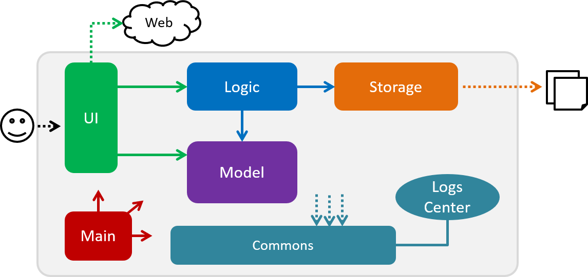
The Architecture Diagram given above explains the high-level design of the App. Given below is a quick overview of each component.
|The .pptx files used to create diagrams in this document can be found in the diagrams folder. To update a diagram, modify the diagram in the pptx file, select the objects of the diagram, and choose Save as picture.
|
Main has only one class called MainApp. It is responsible for,
-
At app launch: Initializes the components in the correct sequence, and connects them up with each other.
-
At shut down: Shuts down the components and invokes cleanup method where necessary.
Commons represents a collection of classes used by multiple other components.
The following class plays an important role at the architecture level:
-
LogsCenter: Used by many classes to write log messages to the App’s log file.
The rest of the App consists of four components.
Each of the four components
-
Defines its API in an
interfacewith the same name as the Component. -
Exposes its functionality using a
{Component Name}Managerclass.
For example, the Logic component (see the class diagram given below) defines it’s API in the Logic.java interface and exposes its functionality using the LogicManager.java class.
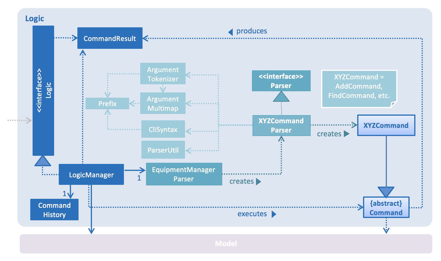
How the architecture components interact with each other
The Sequence Diagram below shows how the components interact with each other for the scenario where the user issues the command delete 1.
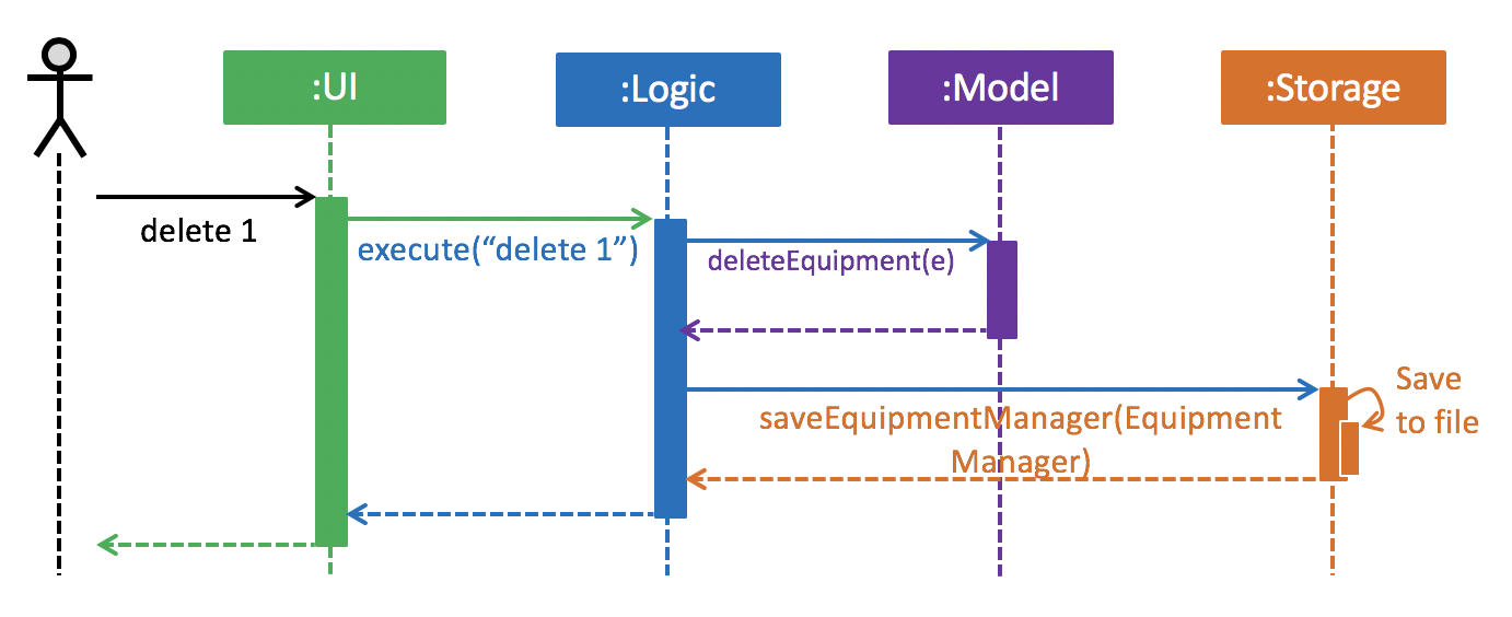
delete 1 commandThe sections below will give more details of each component; UI, Logic, Model and Storage.
3.2. UI component
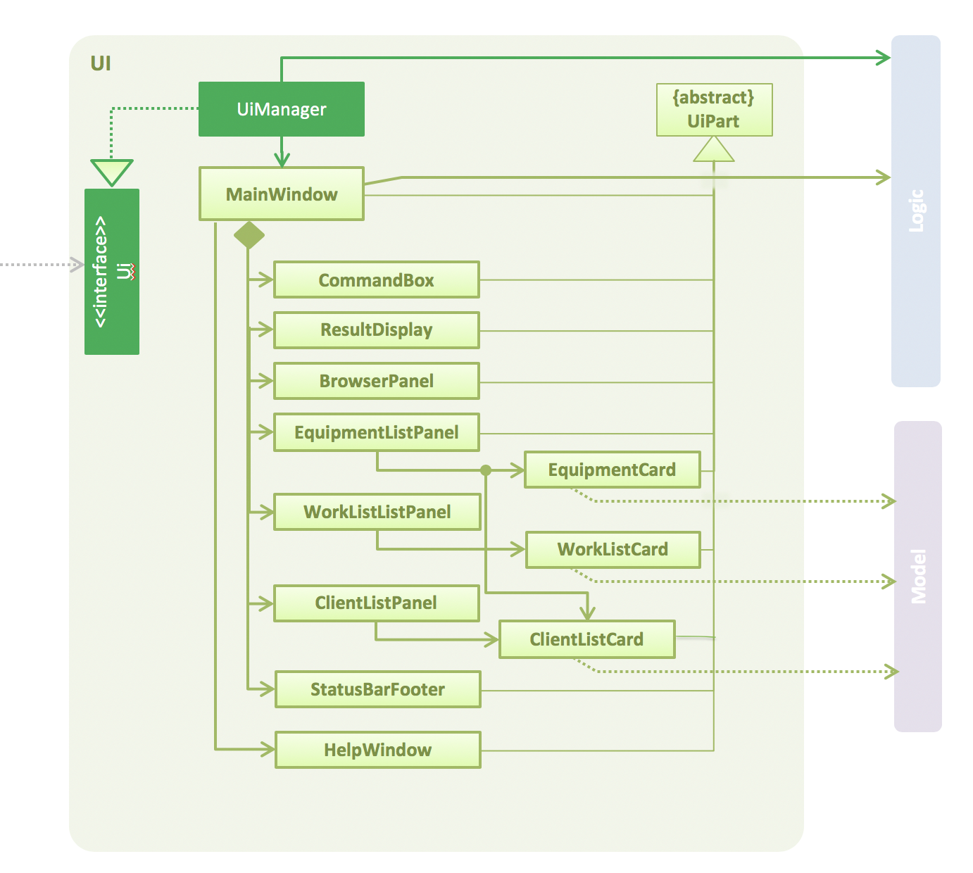
API : Ui.java
The UI consists of a MainWindow that is made up of parts e.g.CommandBox, ResultDisplay, PersonListPanel, StatusBarFooter, BrowserPanel etc. All these, including the MainWindow, inherit from the abstract UiPart class.
The UI component uses JavaFx UI framework. The layout of these UI parts are defined in matching .fxml files that are in the src/main/resources/view folder. For example, the layout of the MainWindow is specified in MainWindow.fxml
The UI component shows webpages e.g. DisplayGmap.html hosted somewhere on the Internet. To host a webpage yourself, you may put your webpage into \docs\staticpages. All pages in \docs\staticpages will be copied to gh-pages branch and hosted on gh-pages.
The UI component,
-
Executes user commands using the
Logiccomponent. -
Listens for changes to
Modeldata so that the UI can be updated with the modified data.
3.3. Logic component

API :
Logic.java
-
Logicuses theEquipmentManagerParserclass to parse the user command. -
This results in a
Commandobject which is executed by theLogicManager. -
The command execution can affect the
Model(e.g. adding an equipment). -
The result of the command execution is encapsulated as a
CommandResultobject which is passed back to theUi. -
In addition, the
CommandResultobject can also instruct theUito perform certain actions, such as displaying help to the user.
Given below is the Sequence Diagram for interactions within the Logic component for the execute("delete 1") API call.
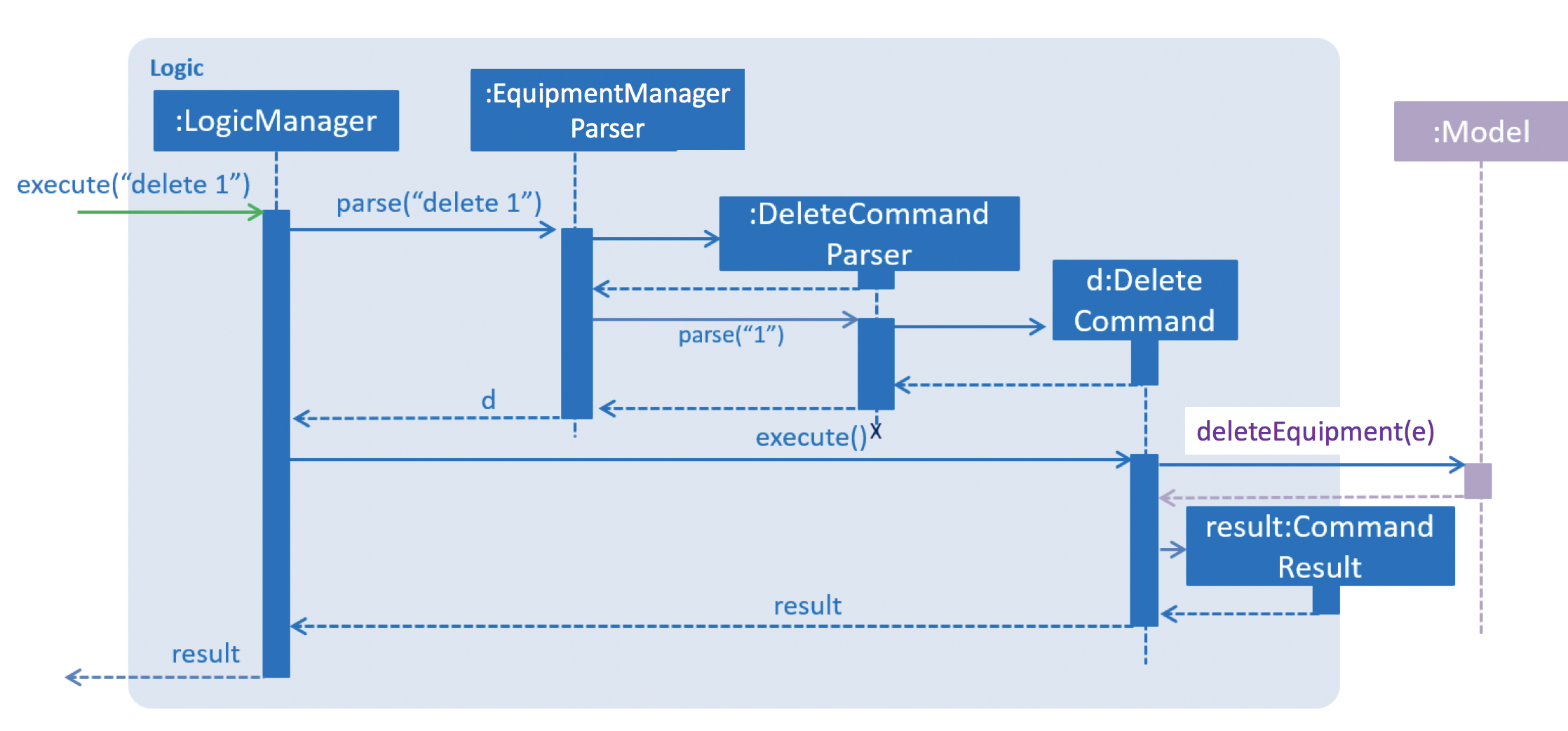
delete 1 Command3.4. Model component
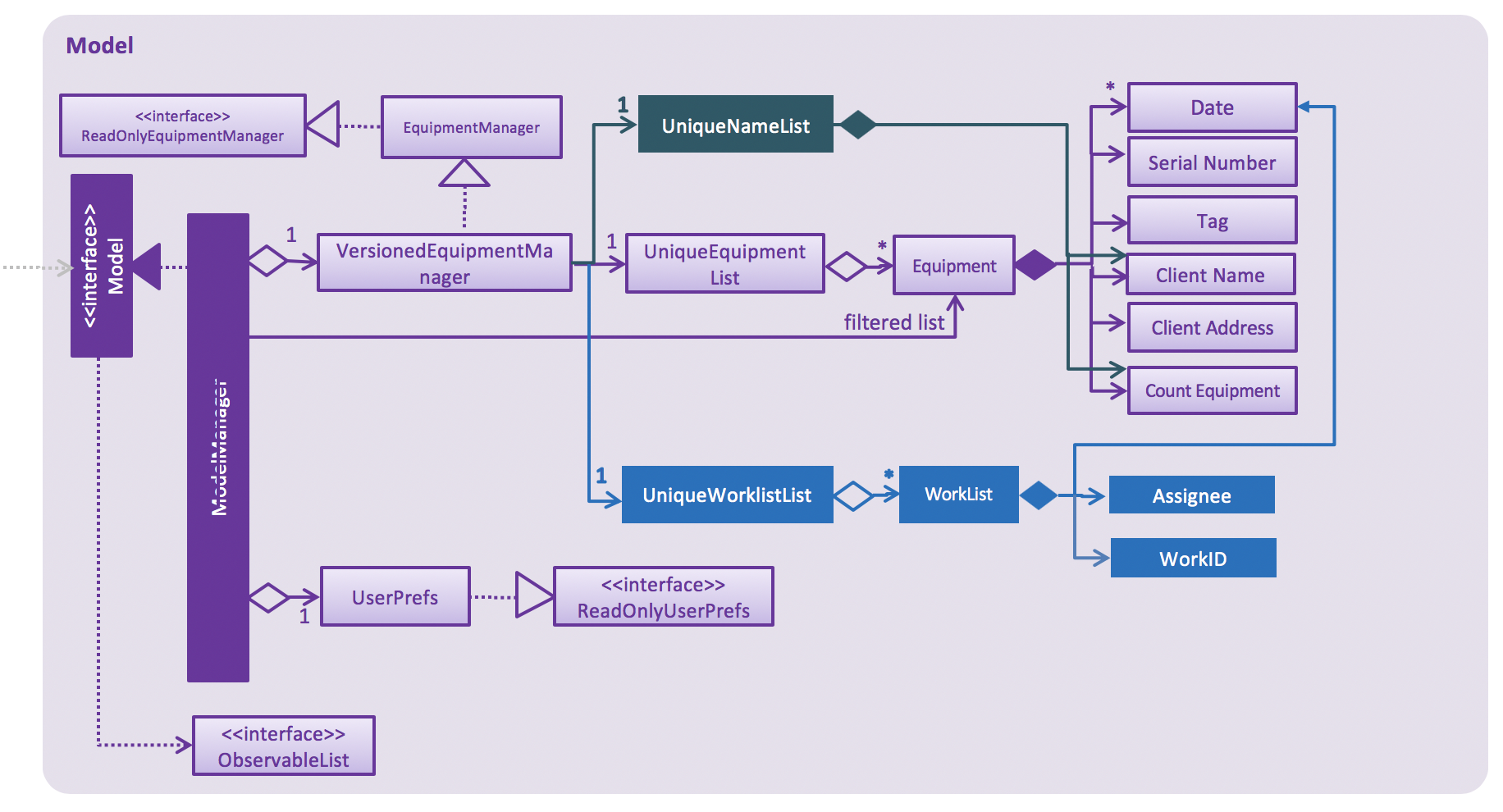
API : Model.java
The Model,
-
stores a
UserPrefobject that represents the user’s preferences. -
stores the Equipment Manager data.
-
exposes an unmodifiable
ObservableList<Equipment>that can be 'observed' e.g. the UI can be bound to this list so that the UI automatically updates when the data in the list change. -
does not depend on any of the other three components.
As a more OOP model, we can store a Tag list in Equipment Manager, which Equipment can reference. This would allow Equipment Manager to only require one Tag object per unique Tag, instead of each Equipment needing their own Tag object. An example of how such a model may look like is given below. |

3.5. Storage component

API : Storage.java
The Storage component,
-
can save
UserPrefobjects in json format and read it back. -
can save the Equipment Manager data in json format and read it back.
3.6. Common classes
Classes used by multiple components are in the seedu.equipment.commons package.
4. Implementation
This section describes some noteworthy details on how certain features are implemented.
4.1. Equipment feature
To provide users with the best understanding on the parameters of equipment in Equipment Manager, this section will provide a brief overview on the equipment details as well as how the details of an equipment are used for multiple features in the design of Equipment Manager. Not forgetting sharing some design considerations to make the best choice for Equipment Manager.
4.1.1. Overview on Equipment details
Equipment Parameters |
Description |
Things to Note |
NAME |
The client’s name who owns the equipment. |
Name should only contain alphanumeric characters and spaces, and it should not be blank. |
PHONE |
The contact number of the client that owns the equipment. |
Phone numbers should only contain numbers, and it should be at least 3 digits long |
DATE |
The due date for which maintenance work on the equipment should be carried out by then. |
Should only contain numbers and hyphens, no blanks allowed. The correct format is dd-MM-yyyy. For example, 03-05-2019 which means 3 May 2019. |
ADDRESS |
The address of the client that owns the equipment. |
|
SERIAL_NUMBER |
The serial number of an equipment |
All equipment have unique serial number and there should not be duplicated serial number. |
4.1.2. Current Usage of Equipment Details
In order to allow users to keep track of the Preventive Maintenance schedule and carry out features provided by Equipment Manager, we have implemented the following commands with the usage of the equipment parameters as mentioned in the previous section.
An example of how the parameters of equipment are used:
-
When user execute the
AddCommandorEditCommand, there are equipment details stored in Equipment Manager. -
When user uses command like
DisplayCommand, Equipment Manager will need to use the address details to provide visual representation of the location of client that owns the equipment. -
When user uses command like
SelectCommand, Equipment Manager will need to use all the equipment details in order to reflect more detailed information on equipment in the Equipment Details Page.
4.1.3. Current Implementation
Using AddCommand mentioned in previous section as an example,
the add equipment mechanism is facilitated by VersionedEquipmentManager which extends the Equipment Manager.
The results of this command will be displayed under Equipment Details panel.
The following sequence diagram shows how the add equipment operation works:
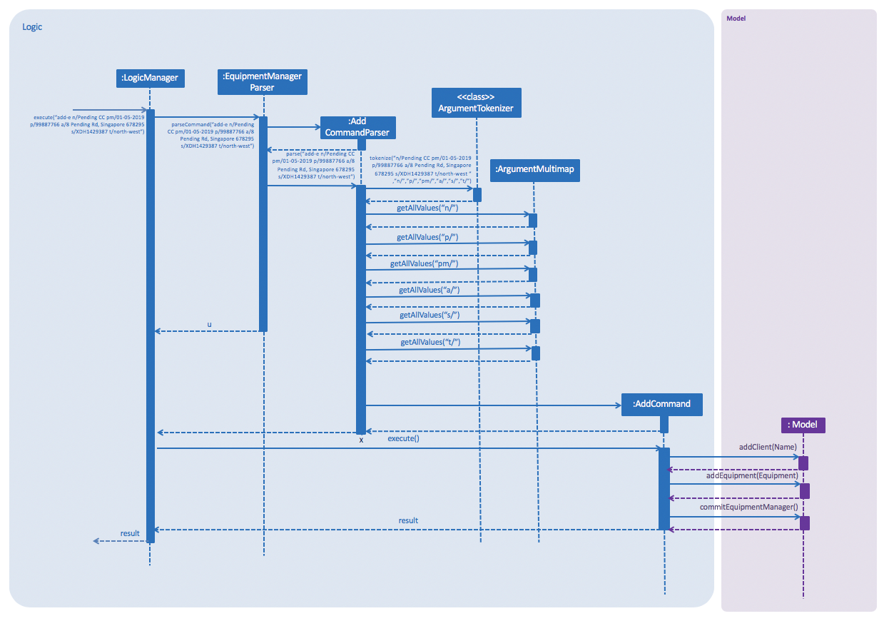
AddCommandGiven below is an example usage scenario of how the adding of equipment details mechanism behaves at each step after carrying out add-e.
Step 1. The user launches the application.
Step 2. The user executes add-e n/Pending CC pm/01-05-2019 p/99887766 a/8 Pending Rd, Singapore 678295 s/XDH1429387 t/north-west command.
Step 3. After EquipmentManagerParser detects add-e as the command word, a AddCommandParser#parse() is called.
Step 4. AddCommand#execute() is then called.
Step 5. The parser will parse all the attributes and add into equipment and client models respectively.
Step 7. The model now contains details of equipment and client, and returns to GUI for display on Equipment details and Client details panels respectively.
With that, you may refer to Section 4.6, “Display feature” to see how Equipment Manager will then use the address details to provide visual representation of the location of client that owns the equipment.
4.1.4. Design Considerations
Aspects: What attributes are important for equipment details to serve the purpose of Equipment Manager.
-
Alternative 1 (current choice): Equipment details contain client details whom own the equipment and equipment unique serial number.
-
Pros: This allows users to know that each equipment has unique serial number and each client can own multiple equipment. Do not have to make major enhancement, save time on backend work.
-
Cons: Might be confusing to user if user is not clear how Equipment Manager works as it may seem like there is duplicated equipment.
-
-
Alternative 2: Equipment details only has serial number and create a seperate class to store store name, phone, address, as client details.
-
Pros: By reading the structure, it is clearer to user that the attributes describe equipment or client.
-
Cons: More backend work needs to be change, takes up a lot of time.
-
4.2. WorkList feature
To help users understand how this feature, WorkList, works in Equipment Manager, this section will give an overview on the WorkList details and how users can interact with WorkList based on the commands implemented in the design of Equipment Manager. It also provides some design considerations to give users an insight of how the current solutions are worked out.
4.2.1. Overview on WorkList details
Attributes |
Description |
Things to Note |
Date |
The tentative maintenance date on the equipments in the WorkList. |
|
Assignee |
The name of the person who is assigned to conduct the maintenance work. |
|
WorkListId |
The id of a WorkList |
All WorkLists should have unique id and there should not be duplicated id. |
4.2.2. Current Usage of WorkList Details
In order to allow users to user WorkList to help them organize their equipments and assign their work, we have implemented several commands as follows with the usage of WorkList details and also some Equipment details.
An example of how the attributes of WorkList are used:
-
When user execute the
AddWorkListCommandorDeleteWorkListCommand, the added WorkList details stored in Equipment Manager, and the deleted WorkList details will be deleted from Equipment Manager. -
When user uses command like
PutCommand, Equipment Manager will help users to put the selected Equipment into the specified WorkList, such that they will know those equipment are in the WorkList with one specified assignee and date. -
When user uses command like
RemoveWorkListCommand, Equipment Manager will remove the selected Equipment from a specified WorkList, it could be the case that users put the equipment into a wrong WorkList, they want to put the equipment into a different WorkList or they just finished maintaining that equipment so they want to remove it from the WorkList.
4.2.3. Current Implementation
Using AddWorkListCommand mentioned in previous section as an example,
the add WorkList mechanism is facilitated by VersionedEquipmentManager which extends the Equipment Manager.
The results of this command will be displayed under WorkList Details panel.
The following sequence diagram shows how the add WorkList operation works:
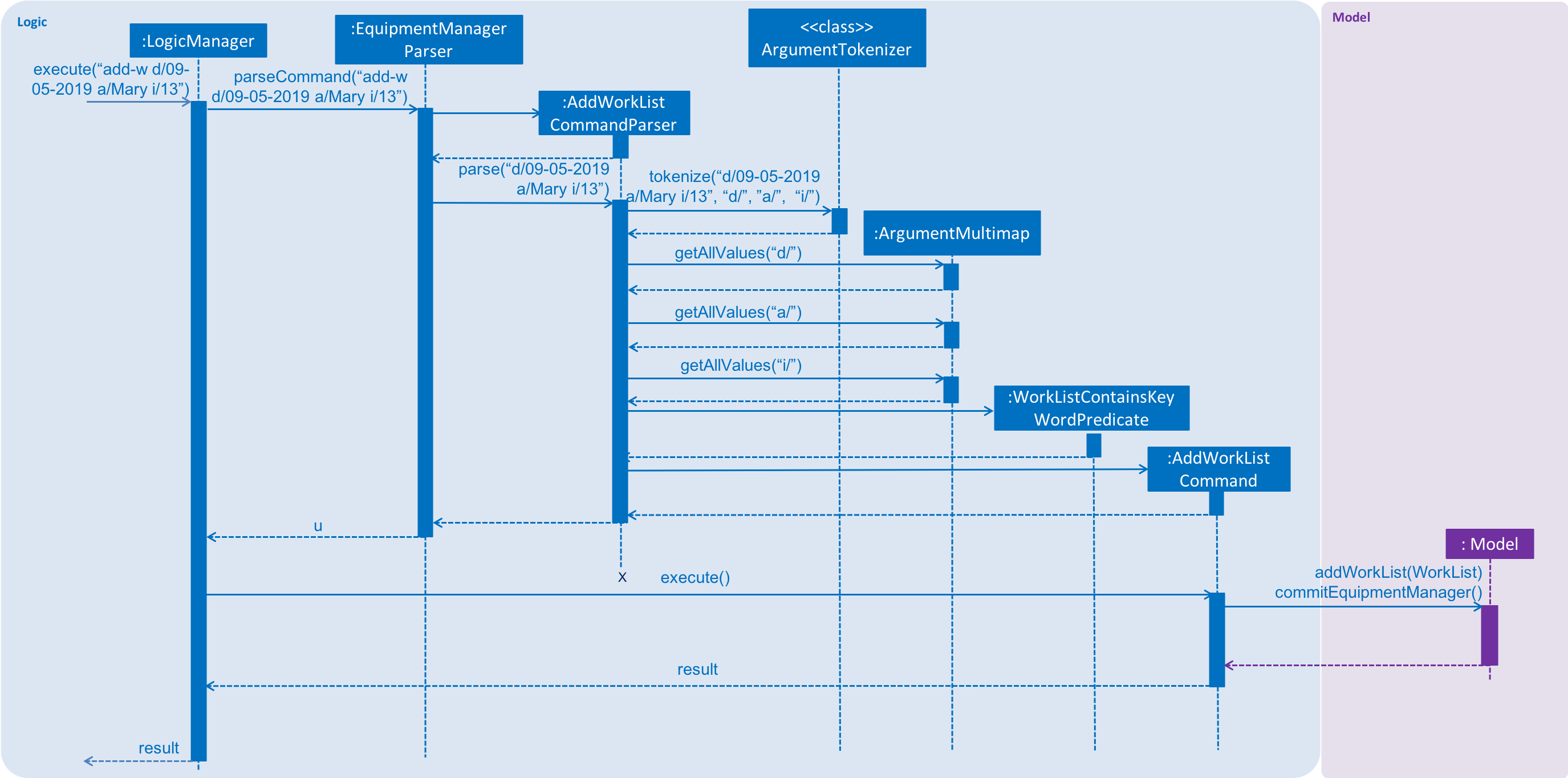
AddWorkListCommandBelow is an example of the step-by-step mechanism of add-w command.
Step 1. The user launches the application.
Step 2. The user executes add-w d/09-05-2019 a/Mary i/13 command.
Step 3. After EquipmentManagerParser detects add-w as the command word, a AddWorkListCommandParser#parse() is called.
Step 4. AddWorkListCommand#execute() is then called.
Step 5. The parser will parse all the attributes and add into WorkList models.
Step 7. The model now contains details of WorkList, and returns to GUI for display on WorkList details panels.
4.2.4. Design Considerations
Aspects: What should be the relationship between the WorkList and Equipments.
-
Alternative 1 (current choice): The WorkList is a independent class and can contains a list of Equipment objects.
-
Pros: This is more organized and it is clear that WorkList contains some Equipments.
-
Cons: Might be confusing the users that why there are so many relationships and these classes are interacting with each other.
-
-
Alternative 2: Equipment is our major work and WorkList is just contains some Serial Numbers just for displaying purposes.
-
Pros: Easy to implement and users are able to know which part they should focusing on more, which is Equipment in this case.
-
Cons: It is hard to do more. If in the future, we intend to do some features like display the equipments in some certain WorkList, then it will be quite hard to implement such a feature.
-
4.3. Client feature
This section describes features specific to client, how having client details contribute to the features in Equipment Manager as well as our design considerations. There may contain some repeated explanation when describing this sections because attributes of client and equipment are being shared in order to for features to be carried out in Equipment Manager.
4.3.1. Overview on Client details
In Equipment Manager, there are Name, Phone, Address attributes stored under Equipment details that identify client details.
-
A client can have 0 to numerous equipment which are identified by unique serial number but an equipment cannot be shared by multiple clients.
-
By using
select-cto select the desired client name in Client details pabel, we can view a list of equipments that are owned by the client.
-
-
Each address tells user where 0 to numerous equipment, which each client owns, are located at.
4.3.2. Current Usage of Client details
As mentioned in Section 4.1.2, “Current Usage of Equipment Details”, the Address which belong to the client address, are used in features like DisplayCommand and SelectCommand.
4.3.3. Current implementation
There is SelectClientCommand that is supported by SelectClientCommandParser.
This selection of client details mechanism is facilitated by VersionedEquipmentManager which extends the Equipment Manager.
Given below is an example usage scenario of how the selection of client details mechanism behaves at each step after carrying out select-c.
Step 1. The user launches the application.
Step 2. The user executes select-c 1 command.
Step 3. After EquipmentManagerParser detects select-c as the command word, a SelectClientCommandParser#parse() is called.
Step 4. SelectClientCommand#execute() is then called and set the selected client in the model with the filtered client list.
Step 5. Using the filter feature, the model will use the Name attributes, filter the equipment list accordingly and displays the client’s equipment in the Equipment details panel.
Step 7. The model now contains additional client name and returns to GUI for display on Client details panel respectively. The model also contains filtered client’s equipment and returns the GUI for display on Equipment details panel.
The figure in Current Implementation of Section 4.1, “Equipment feature” also explains how AddCommand contributes to the results shown in Client Details panel.
|
4.3.4. Design Considerations
Refer to the Design Considerations in Section 4.1, “Equipment feature” as we went through the same design considerations to come out with equipment and client details separation.
Aspects: With a list of client displayed in Client details panel, how should the client’s equipment details be displayed?
-
Alternative 1 (current choice): Making use of the
filtercommand to show client’s equipment-
Pros: Making use of existing Equipment details panel. Easier to implement with lesser changes to the storage, logic, model and ui components within the time constraint.
-
Cons: select followed by a filter command is stored in the history even though user did not use filter command. This is the trade off.
-
-
Alternative 2: Add a new equipment panel and card for displaying client’s equipment when selecting the client
-
Pros: Do not have the issue of filter command being tracked in history even though user did not use the filter command.
-
Cons: Too many different panels in one main window display may cause confusion and lower user’s experience.
-
4.4. Filter feature
4.4.1. Introduction
We have implemented a FilterCommand that allow users to filter the equipment list with the specified fields.
The filter feature allow users to filter the equipment list with any specified fields, and also can filter by multiple fields.
The FilterCommand is able to filter the equipment list according to the user’s preference at a time.
4.4.2. Current Implementation
The filter mechanism is supported by FilterCommandParser. It implements Parser that implements the following operation:
-
FilterCommandParser#parse()- Checks the arguments for empty strings and throws a ParseException if empty string is found. It then splits the arguments usingArgumentTokenizer#tokenize()and returns an ArgumentMultimap. Keywords of the same prefix are then grouped usingArgumentMultimap#getAllValues().
The filter mechanism is also facilitated by FilterCommand. It extends Command and implements the following operation:
FilterCommand#execute() — Executes the command by updating the current FilteredPersonList with the EquipmentContainsKeywordPredicate.
EquipmentContainsKeywordsPredicate takes in the lists of keywords for the following:
-
Name
-
Address
-
Date
-
Phone
-
Tags
-
Serial Number
The following sequence diagram shows how the filter operation works:
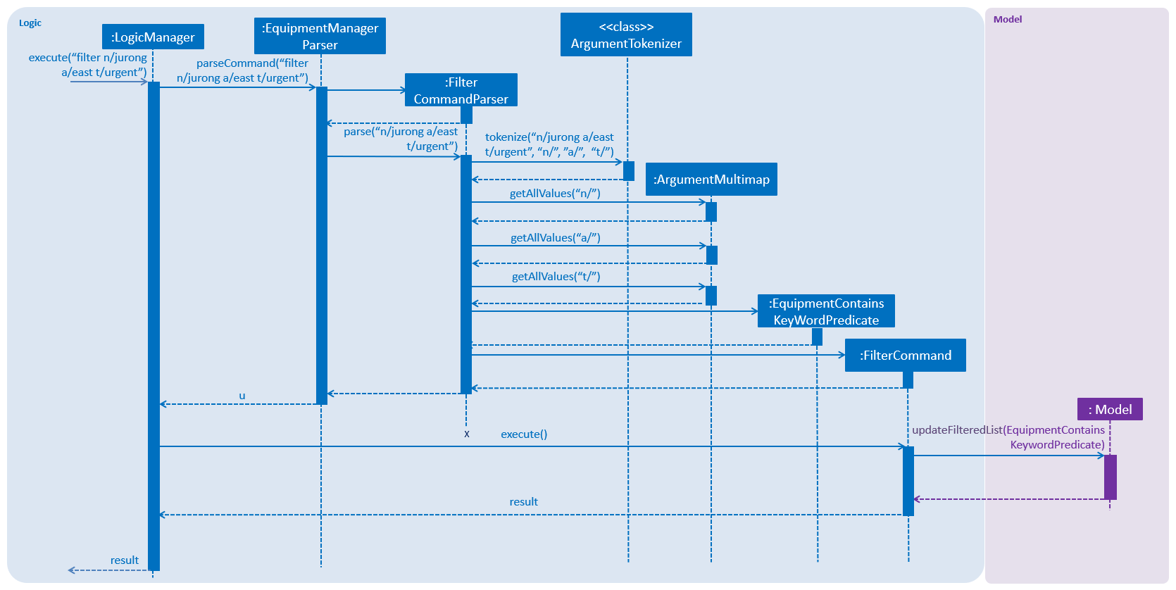
Example
Given below is an example usage scenario of how the filter mechanism behaves at each step when filtering.
Step 1. The user launches the application.
Step 2. The user executes filter n/jurong a/west t/urgent command to get all fields whose equipment contains the keywords
Step 3. After EquipmentManagerParser detects filter as the command word, a FilterCommandParser#parse() is called and
the EquipmentContainsKeywordsPredicate is constructed with the arguments of the filter command.
Step 4. FilterCommand#execute() is then called.
Step 5. The entire equipment list is filtered by the predicate EquipmentContainsKeywordsPredicate.
Step 6. Then, EquipmentContainsKeywordsPredicate checks that the Equipment Manager has either the respective
attributes - serial number, tags, address, name, preventive maintenance date, phone.
Step 7. The argument is filtered against the predicate and returned to the GUI.
FilterCommand only filters the equipment list.
|
4.4.3. Design Considerations
Implementation of FilterCommand
-
Alternative 1 (current choice): Require user to prepend every keyword argument with the appropriate attribute prefix. Supports multiple fields in the same command.
-
Pros: It is easy to implement and easy to match keyword against an equipment if the matching attribute is known.
-
Pros: User has more control over the results returned.
-
Pros: User can also filter by multiple fields. e.g:
filter n/jurong t/west -
Cons: User is required to type slightly more.
-
Cons: It only filters the equipment list.
-
-
Alternative 2: filter by specific fields
-
Pros: It is easy to implement and it is also consistent with how
FilterCommandworks. -
Cons: User has less control over the results returned.
-
Cons: User can input anything and the results returned is not specific by type.
-
-
Alternative 3: filter by tags
-
Pros: It is more specific and more restricted.
-
Cons: More difficult to implement
-
Cons: Too restricted as it is only filtered by tags.
-
4.5. Sort feature
4.5.1. Introduction
We have implemented a SortCommand that allow users to sort the equipment list with specific field.
The entries in the equipment list is ordered to the time when the entry is entered into the application by default such that the entry entered first is at the top of the equipment list and the latest entry entered is at the bottom of the equipment list.
The sort mechanism allows user to view the equipment list according to their preferences.
The SortCommand is able to sort the equipment list according to the user’s preferences at a time.
4.5.2. Current Implementation
The sort command sorts the list by specified field in lexicographical order.
Comparators that implement java.util.Comparator interface are used in the sort mechanism to perform the comparsion.
The sort mechanism is supported by SortCommandParser. It implements Parser that implements the following operation:
-
SortCommandParser#parse()- Checks the arguments for empty strings and throws a ParseException if empty string is found. It then splits the arguments and checks if the next string is a valid field, else, it will throw a ParseException.
Valid fields:
-
name
-
date
-
phone
-
serial
The following sequence diagram shows how the sort operation works:
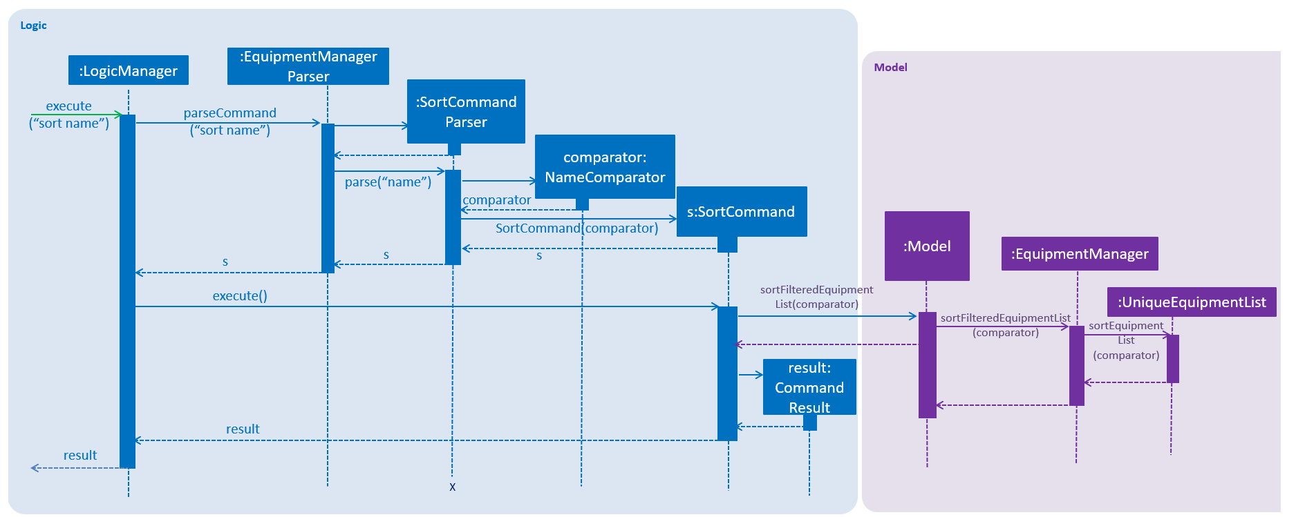
Example
Given below is an example usage scenario of how the sort mechanism behaves at each step when sorting.
Step 1. The user launches the application.
Step 2. The user executes sort name command to sort the equipment list by name.
Step 3. SortCommandParser#parse() creates a new NameComparator() object and passes it into SortCommand.
Step 4. EquipmentManager#sortEquipmentList(comparator) calls UniqueEquipmentList#sortEquipmentList(comparator), which then
uses FXCollection’s static method sort() to sort the equipment list by name.
Step 5. The list is sorted by specified field (name) and returned to the GUI.
Test cases:
-
Input:
sort
Output: An error message will be displayed to show what are the fields available.
-
Input:
sort name
Output: The list is sorted by the name in alphabetical order.
-
Input:
sort date
Output: The list is sorted in ascending order by the the preventative maintenance date of the equipment.
-
Input:
sort phone
Output: The list is sorted in ascending order by the phone number of the client.
-
Input:
sort serial
Output: The list is sorted in ascending order by the serial number of the equipment.
SortCommand only sorts the equipment list.
|
4.5.3. Design Considerations
Implementation of SortCommand
-
Alternative 1 (current choice): Sorts by specific field by using the Comparator interface.
-
Pros: Sorting can be done based on different fields (name, date, phone number and serial number)
-
Cons: A new class that implements the interface Comparator needs to be created for the fields.
-
-
Alternative 2: Sort by client name
-
Pros: Overall list is sorted fully by client name
-
Cons: Unable to sort other specific fields such as serial number of the equipment.
-
4.6. Display feature
The display feature allow users to view the location of all equipment in the current shown list on map.
4.6.1. Current Implementation
The following activity diagram shows each action is done by which component.
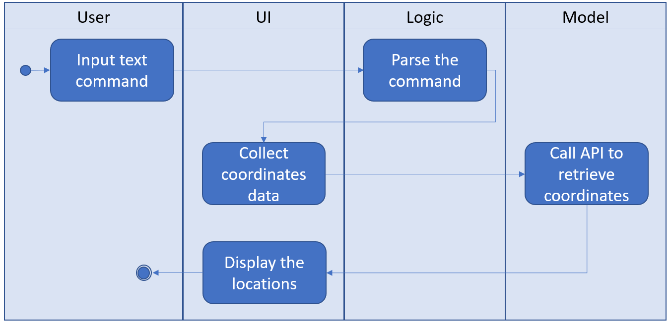
The following sequence diagram shows how the display operation works:
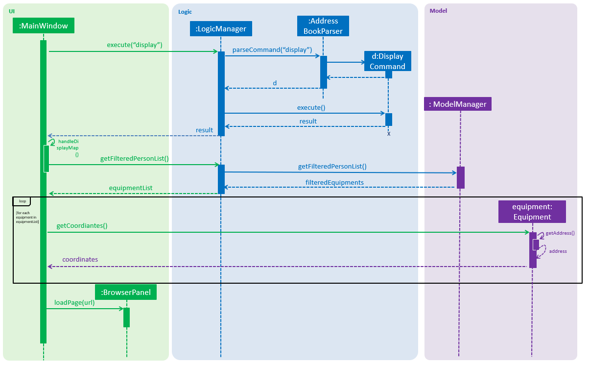
Step 1. The user launches the application, the list of equipment will show in UI and stored in the Model.
Step 2. The user executes display command to show all the equipment on the map. The execution of display command will return a CommandResult indicating display which can be checked by CommandResult#isDisplayMap(). The MainWindow will check if the CommandResult is a display map command. Then MainWindow#handleDisplayMap will be called. MainWindow#handleDisplayMap will call Logic#getFilteredPersonList() to get the equipment list, and then call Equipment#getCoordiantes() on each equipment to get its coordinates.
Step 3. The Equipment#getCoordiantes() calls to Google Map Geocoding API with the address returned by Equipment#getAddress(). The API will return the coordinates of the address. This will be returned as the coordinates of the equipment. The coordinates will be stored for future use.
Google Map Geocoding API is not free to use. You need to have your own API key to use the API. You may check Google Map Platform - Geocoding Service
|
Step 4. The coordinates are constructed to form a URL and call a web page in BrowserPanel to display the map. Currently the map is stored as /docs/staticpages/DisplayGmap.html which will be copied and published by Travis CI robot to github pages. You may either use your own github pages URL by changing BrowserPanel#MAP_MULTIPLE_POINT_BASE_URL to your own github pages URL, or use the current URL published by CS2103-AY1819S2-W10-3 team.
Step 5. The webpage receive the coordinates in parameter form. It will first parse the parameters. The standard form of parameters is ?coordinates=[[1.3012,103.1233], [1.4323, 103.2012]]&otherfields=["abc", "def"]. The number of elements in other parameters must match the number of elements in the coordinates parameter. The map may be extended to handle more functions, however the current parameter parser can only handle parameters in this standard format. For now, only coordinates are used, other parameters will be ignored.
4.6.2. Design Considerations
Aspect: How to display the base map
-
Alternative 1 (current choice): Use separate web page, pass the coordinates as parameters.
-
Pros: Easy to implement. Flexible to add more functions. Many JavaScript libraries can be used.
-
Cons: Unexpected behaviors would happen if the WebEngine cannot display the web page properly.
-
-
Alternative 2: Use third party JavaFX map libraries.
-
Pros: No unexpected behaviors, and more consistent running on different platforms.
-
Cons: Harder to implement, less flexibility, and limit to extensions.
-
Aspect: Which JavaScript Map library to use
-
Alternative 1 (current choice): Use Google Map JavaScript API
-
Pros: Easy to embed other Google Map APIs, and work better with JavaFX built in browser.
-
Cons: Harder to customize the style of map, marker and etc. (Compared to
Alternative 2)
-
-
Alternative 2: Use MapBox GL JS.
-
Pros: Easy to have customized view, better looking themes.
-
Cons: Works bad in JavaFX default built in browser, and harder to cooperate with Google API.
-
Aspect: Call Geocoding API to get coordinates in main application or built in browser
-
Alternative 1 (current choice): In main application
-
Pros: Addresses are reusable, i.e. only need to call
Geocoding APIonce for each equipment. -
Cons: Harder to make the function call, and increase the hang up time when many equipments do not have coordinates retrieved.
-
-
Alternative 2: In built in browser with JavaScript
-
Pros: User will get instant response and see the base map after entering the command, although the actual display will come later.
-
Cons: Addresses will not be reusable, each time user enter
displaywould callGeocoding APIfor each equipment and incur high API costs.
-
4.7. Route feature
The route feature allow users to know the best order to traverse through all equipments listed in the equipment panel. The order will be shown on the map.
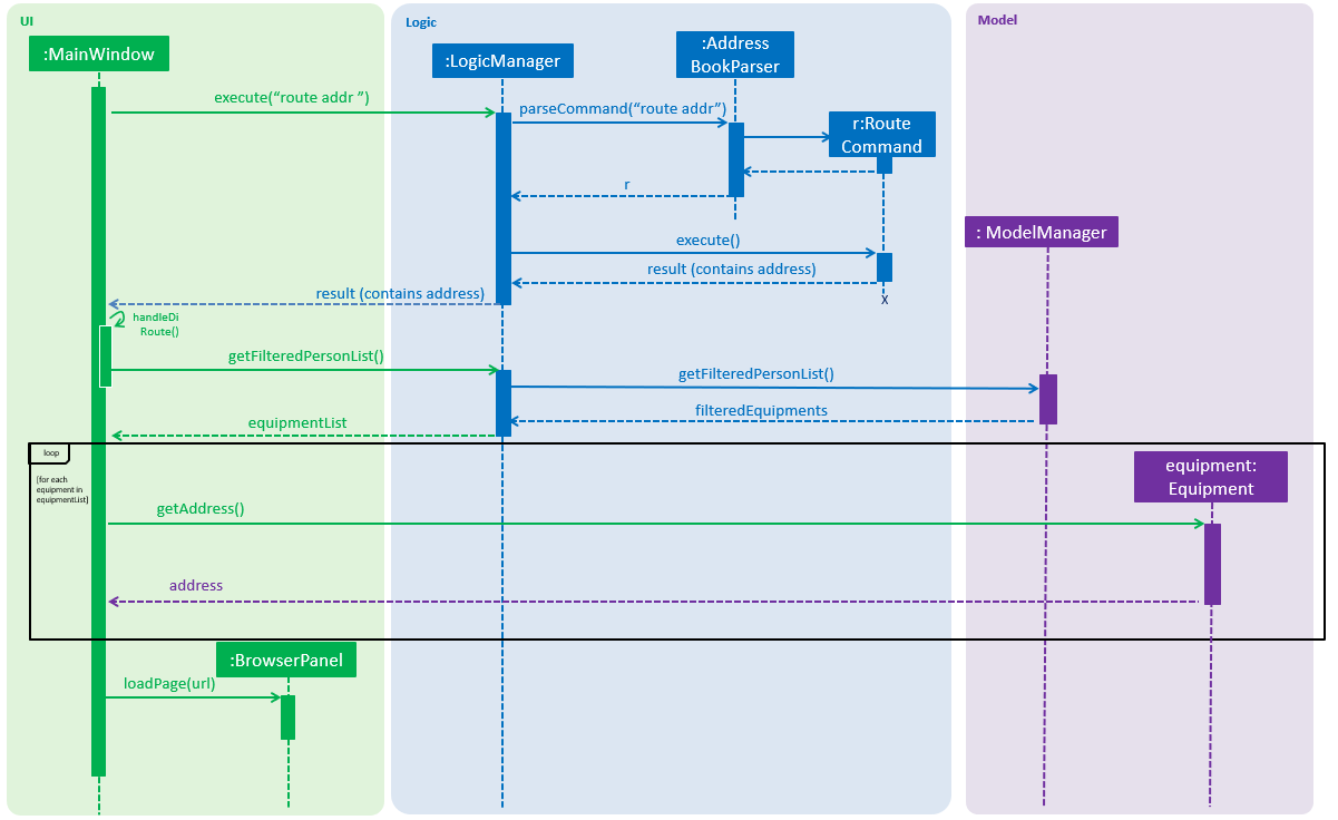
The following sequence diagram shows how the display operation works:
4.7.1. Current Implementation
Step 1. The user launches the application, the list of equipments will show in UI and stored in the Model.
Step 2. The user executes route command together with the origin address to display the route starting from the origin address, travel through all equipments, and go back to the origin address. The execution of route command will return a CommandResult indicating this is an route command which can be checked by CommandResult#isRoute(). The CommandResult also contains start address parameter called routeAddress of Address type. The MainWindow will check if the CommandResult is a route command. Then MainWindow#handleRoute will be called.
Step 3. MainWindow#handleRoute will call Logic#getFilteredPersonList() to get the equipments list, and then call Equipment#getAddress() on each equipments to get its address.
Step 4. The addresses are constructed to form a URL and call a web page in BrowserPanel to display the map. Currently the map is stored as /docs/staticpages/DisplayRoutes.html which will be copied and published by Travis CI robot to github pages. You may either use your own github pages URL by changing BrowserPanel#MAP_ROUTE_BASE_URL to your own github pages URL, or use the current URL published by CS2103-AY1819S2-W10-3 team.
Step 5. The web page receive the addresses in parameter form. It will first parse the parameters. The standard form of parameters is ?address=["Address 1", "Address 2"]&start="Origin address"&end="Destination address". The order of parameters does not matter.
Step 6. The JavaScript code in the web page will call Google Map JavaScript API to calculate the best route to each addresses, and display the route on the map.
Google Map JavaScript API is not free to use. You need to have your own API key to use the API. You may check Google Map Platform - Maps JavaScript API
|
4.7.2. Design Considerations
Aspect: Passing addresses or coordinates to web page
-
Alternative 1 (current choice): Passing addresses to web page
-
Pros: Better accuracy, as addresses would interpreted more accurately than coordinates when involving routing.
-
Cons: Worse data reusability, waste API calls, because the data retrieved from the
Google Map JavaScript APIcannot be send back to the main application and stored.
-
-
Alternative 2: Passing coordinates to the web page
-
Pros: Save some API calls.
-
Cons: Worse accuracy.
-
Calling Google Map JavaScript API to retrieve the route is much more expensive than calling Geocoding API to retrieve the coordinates. Thus, it is fair to prioritize to utilize function of Google Map JavaScript API to retrieve the route.
|
Aspect: How to pass the origin address to UI
-
Alternative 1 (current choice): Passing as a parameter in
CommandResult-
Pros: Minimal code changes.
-
Cons: Need to create more constructor of
CommandResult, and it may get harder to understand the usage of these constructors.
-
-
Alternative 2: Storing as a field in
Model-
Pros: Easier to understand and use.
-
Cons: Require more code changes because changing
Modelinterface will break many classes and tests.
-
Aspect: How to pass extra parameters to CommandResult
-
Alternative 1 (current choice): Use overloading of the constructor
-
Pros: No need to change the caller code of the constructor, decrease the possibility of code conflicts when merging with teammates' code.
-
Cons: As more fields are added to
CommandResult, more constructors will be added. As a result, it may confuse future developers.
-
-
Alternative 2: Directly modify the
CommandResultclass and its constructor signature-
Pros: More straightaway and easier to understand.
-
Cons: Changing the constructor signature also need to change all the caller functions. So it requires changes of many classes which may bring code conflicts.
-
4.8. User Interface (UI)
The UI of Equipment Manager is a combination of JavaFX, HTML and CSS. This section describes our overall current implementation for UI as well as showing our thinking process for the UI in designs considerations section.
4.8.1. Current implementation
Launch the Application
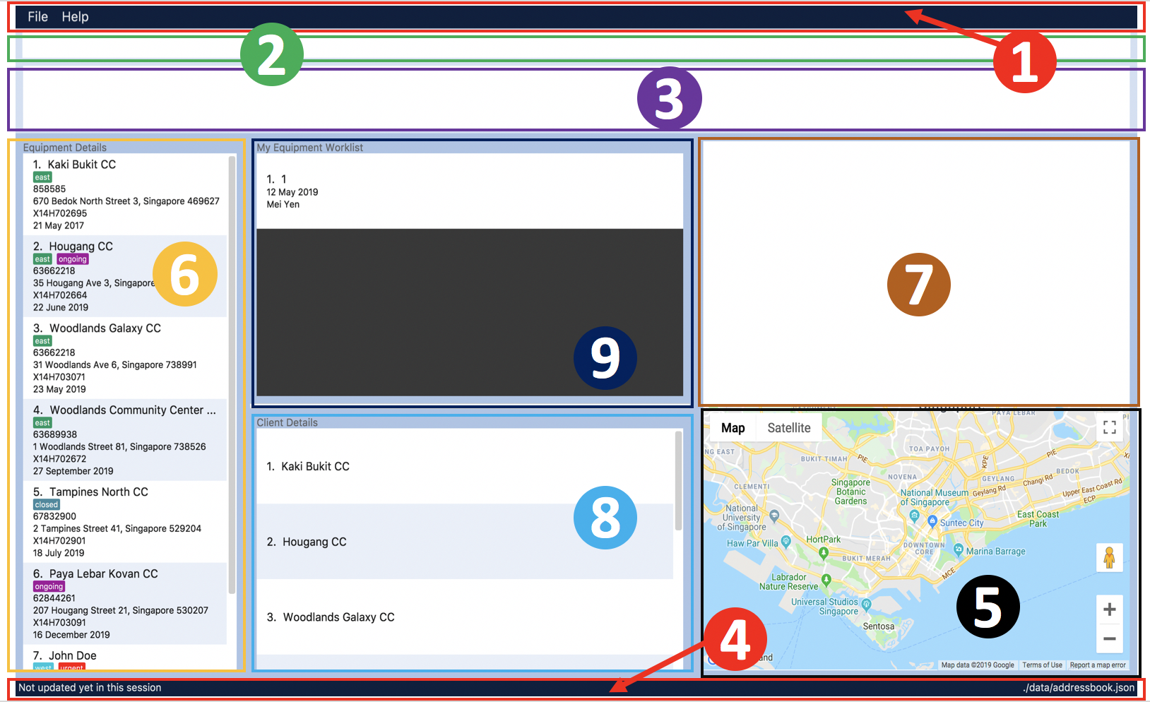
The figure above depicts the interface the user see when the user launches the application. The user should be greeted by 9 different regions:
Regions of Application |
Purpose |
[1] Menu Bar |
Allow users to click |
[2] Command Box |
User enters the command in the command box. Refer to User Guide to learn all the available commands. |
[3] Message box |
The message box that shows the result after a command has been executed. |
[4] Status Bar |
Show the total number of equipment in the Equipment Manager. |
[5] Google Map |
Google map serves as a visual representation for where equipment are at as well as showing user the possible routes to take. |
[6] Equipment details panel |
This panel shows summarized details on equipment |
[7] Equipment Details Page |
This is a HTML page where it shows more detailed information on an equipment. |
[8] Client Details panel |
This panel shows specifically information related to client such as the name and how many equipment the client owns. |
[9] My Work List panel |
This panels shows the work schedule of a person when the user assigns equipment whom the user want to carry out preventive maintenance work. |
Showcasing Client details
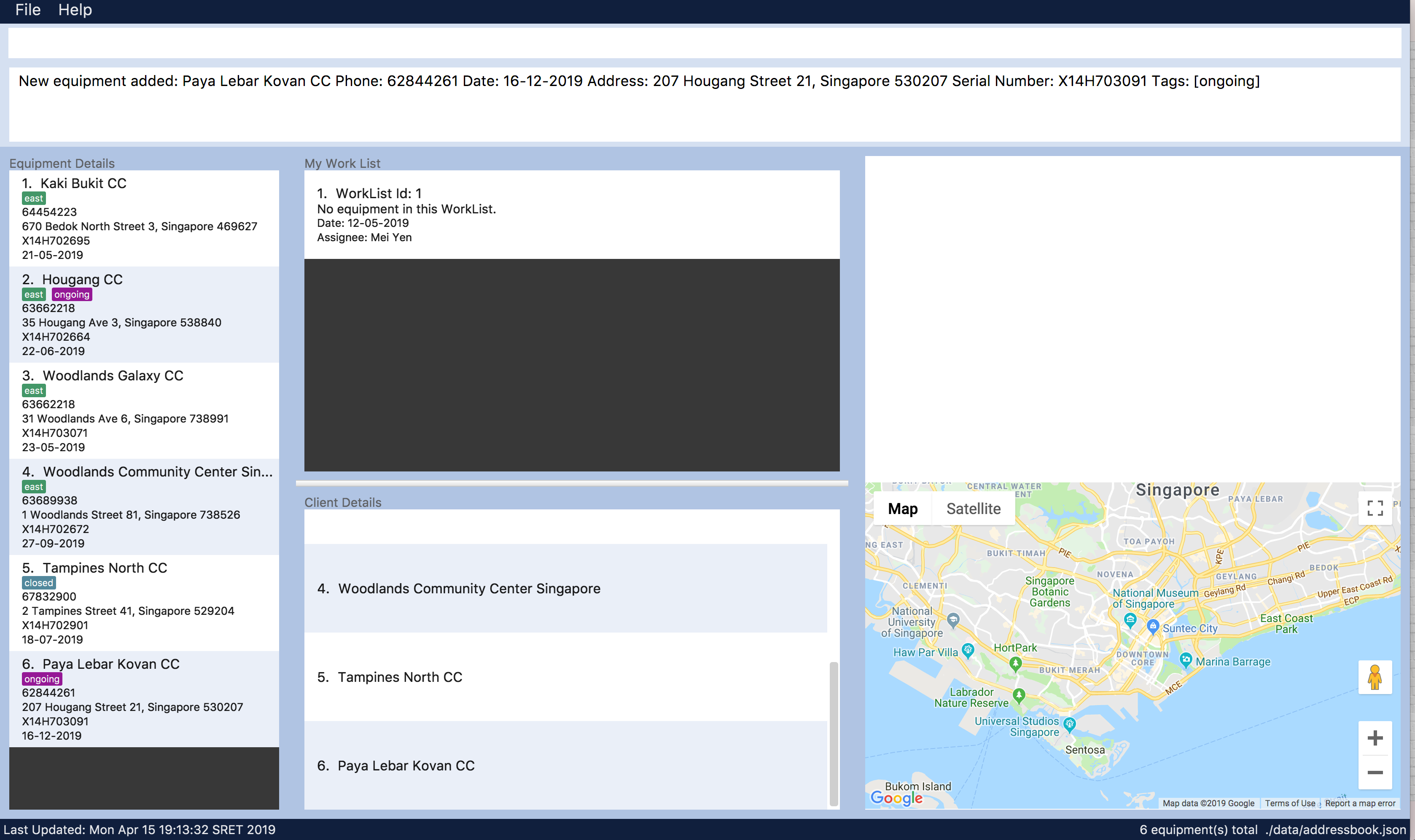
To avoid cluttering to many information in Equipment details panel, we decided to categorise information related to clients into Client details panel such as showing all the unique client names in Equipment Manager as seen in the figure below.
Showcasing Equipment details and locations
Similarly, there are many information to be shown in Equipment details panel. Hence, as seen in the figure below, we created a HTML page to show more information on equipment. This means that there are some information not shown in Equipment details panel but will instead be shown in Equipment Details Page.
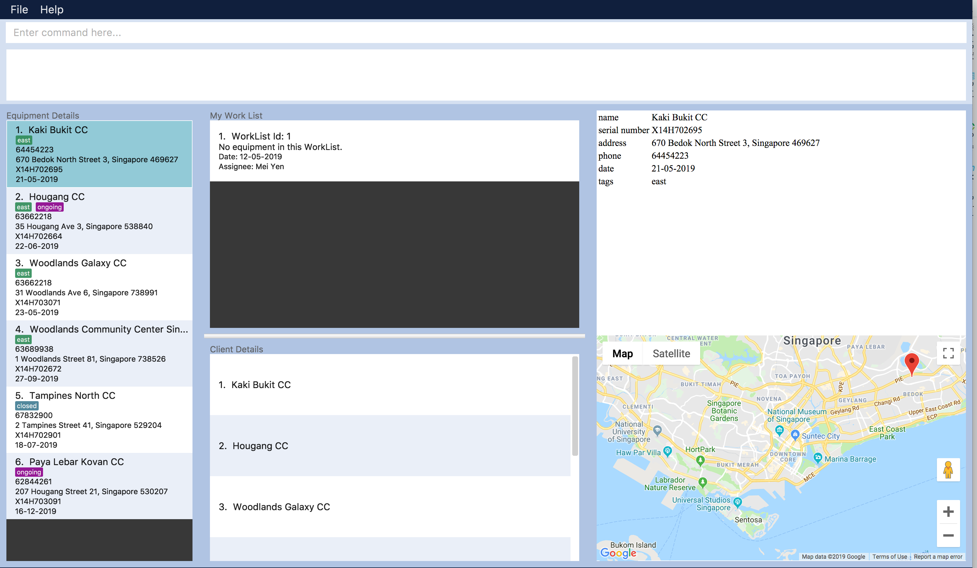
One of our main feature of Equipment Manager is the ability to have a visual representation on 1 or more equipment in a Google Map.
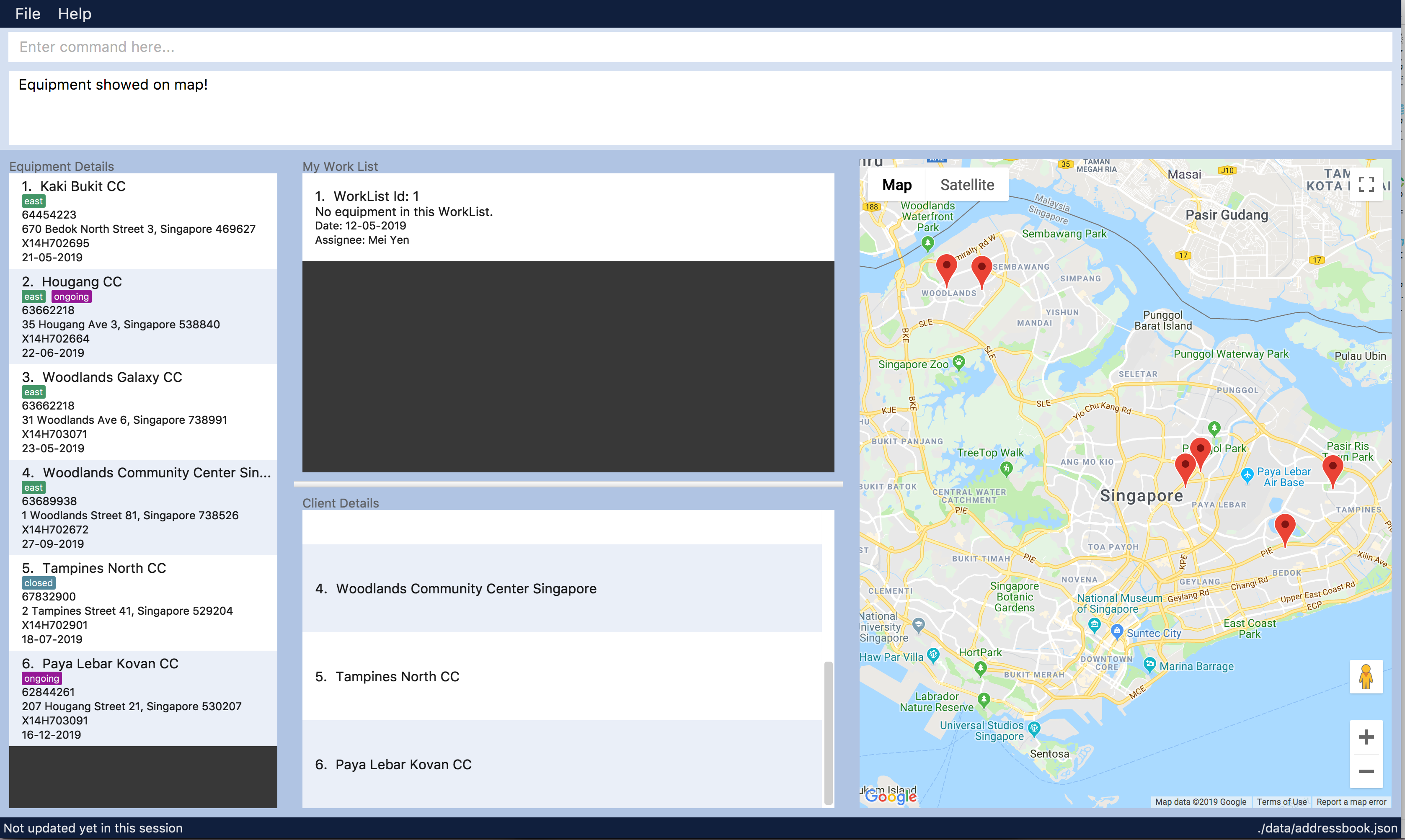
display feature on UIAs seen in the above figure, entering display command will allow a visual representation of all equipment locations in the Equipment Manager data storage onto Google Map.
This is one of our main feature of Equipment Manager where we provide users to view either 1 equipment location at a time by entering select INDEX or simply by clicking onto the an equipment in Equipment details panel.
4.8.2. Design Considerations
Aspects: Information to be displayed on respective panels
-
Alternative 1: Showing all client, worklist, equipment resulting commands in one panel.
Pros |
Lesser panels will have lesser clutter to user experience. UX experience will be better. |
Cons |
Harder to implement. Require to work with label that is able to change when panel has changed to serve other purposes such as from displaying equipment details to worklist details in the same panel. |
-
Alternative 2 (Current Choice): Show client, worklist, equipment resulting commands in 3 respective panels.
Pros |
Easier to implement. To avoid confusion on which panel is being updated, we added a header label above each panel. |
Cons |
Application looks more cluttered with more dividers for different panels. |
4.9. Undo/Redo feature
4.9.1. Current Implementation
The undo/redo mechanism is facilitated by VersionedEquipmentManager.
It extends EquipmentManager with an undo/redo history, stored internally as an EquipmentManagerStateList and currentStatePointer.
Additionally, it implements the following operations:
-
VersionedEquipmentManager#commit()— Saves the current Equipment Manager state in its history. -
VersionedEquipmentManager#undo()— Restores the previous Equipment Manager state from its history. -
VersionedEquipmentManager#redo()— Restores a previously undone Equipment Manager state from its history.
These operations are exposed in the Model interface as Model#commitEquipmentManager(), Model#undoEquipmentManager() and Model#redoEquipmentManager() respectively.
Given below is an example usage scenario and how the undo/redo mechanism behaves at each step.
Step 1. The user launches the application for the first time. The VersionedEquipmentManager will be initialized with the initial Equipment Manager state, and the currentStatePointer pointing to that single equipment manager state.

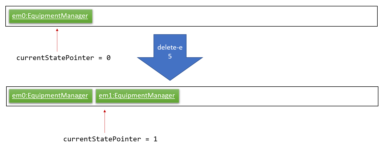
Step 2. The user executes delete-e 5 command to delete the 5th equipment in the Equipment Manager. The delete-e command calls Model#commitEquipmentManager(), causing the modified state of the Equipment Manager after the delete-e 5 command executes to be saved in the equipmentManagerStateList, and the currentStatePointer is shifted to the newly inserted *Equipment Manager*r state.
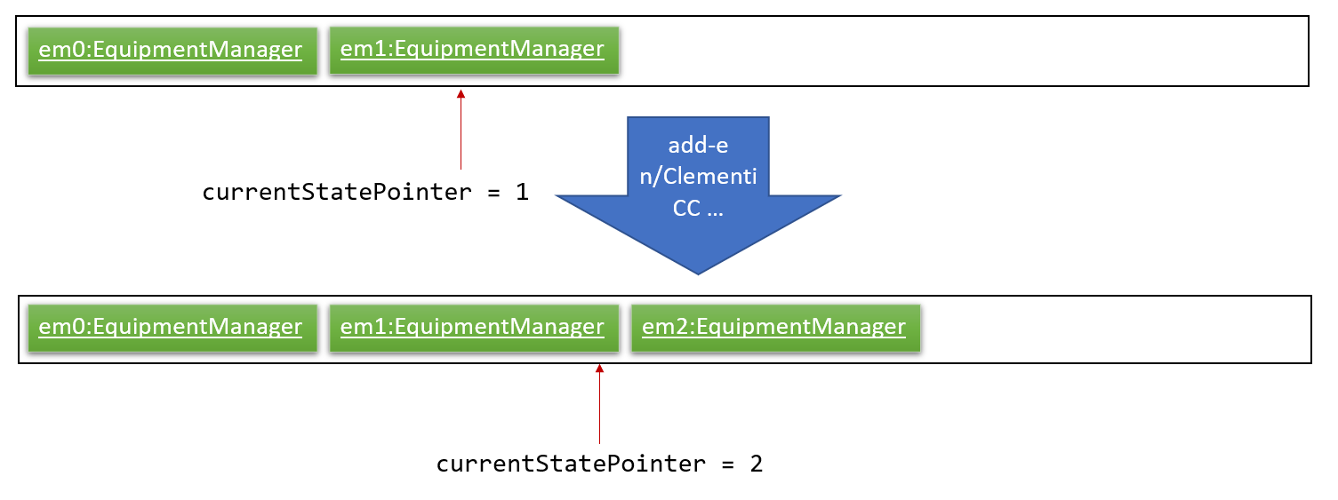
Step 3. The user executes add-e n/Clementi CC … to add a new equipment. The add command also calls Model#commitEquipmentManager(), causing another modified Equipment Manager state to be saved into the equipmentManagerStateList.
If a command fails its execution, it will not call Model#commitEquipmentManager(), so the Equipment Manager state will not be saved into the equipmentManagerStateList.
|
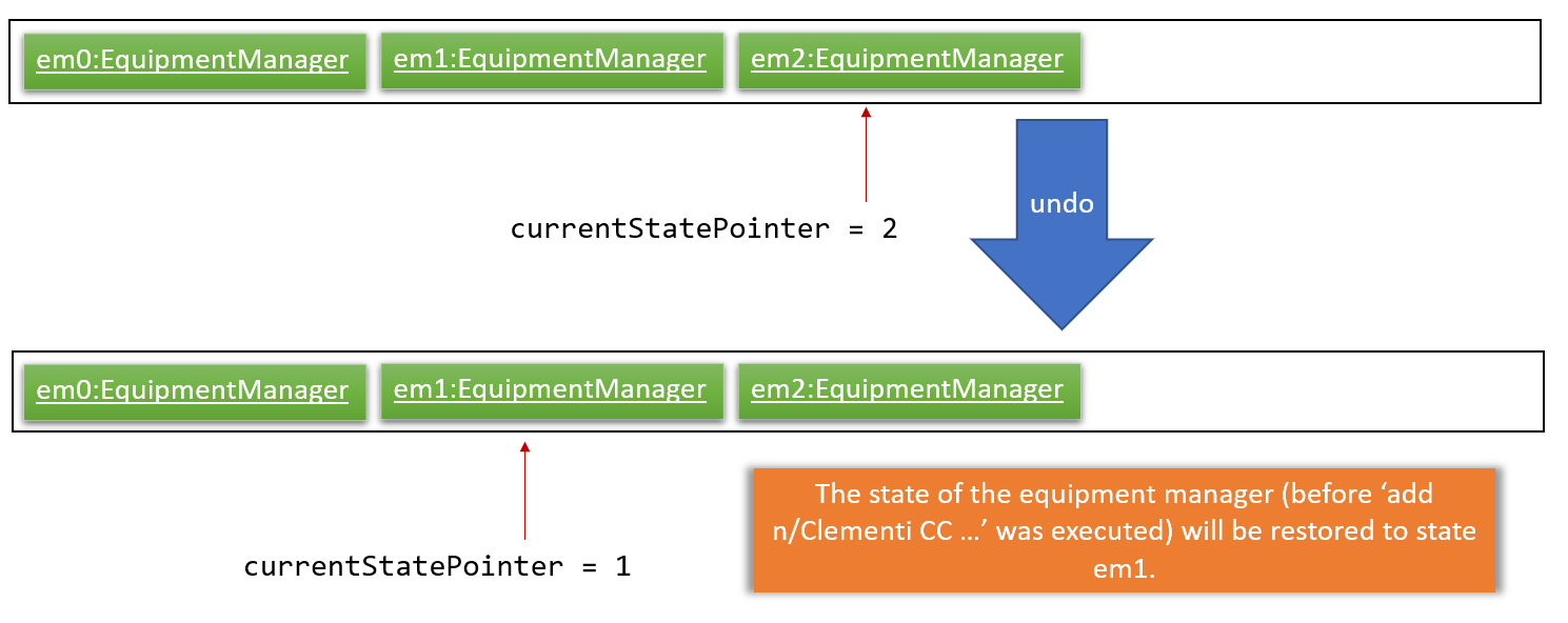
Step 4. The user now decides that adding the equipment was a mistake, and decides to undo that action by executing the undo command. The undo command will call Model#undoEquipmentManager(), which will shift the currentStatePointer once to the left, pointing it to the previous Equipment Manager state, and restores the Equipment Manager to that state.
If the currentStatePointer is at index 0, pointing to the initial Equipment Manager state, then there are no previous Equipment Manager states to restore. The undo command uses Model#canUndoEquipmentManager() to check if this is the case. If so, it will return an error to the user rather than attempting to perform the undo.
|
The following sequence diagram shows how the undo operation works:
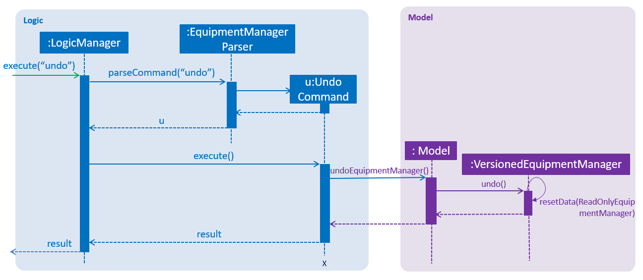
The redo command does the opposite — it calls Model#redoEquipmentManager(), which shifts the currentStatePointer once to the right, pointing to the previously undone state, and restores the Equipment Manager to that state.
If the currentStatePointer is at index equipmentManagerStateList.size() - 1, pointing to the latest Equipment Manager state, then there are no undone Equipment Manager states to restore. The redo command uses Model#canRedoEquipmentManager() to check if this is the case. If so, it will return an error to the user rather than attempting to perform the redo.
|
Step 5. The user then decides to execute the command list. Commands that do not modify the Equipment Manager, such as list, will usually not call Model#commitEquipmentManager(), Model#undoEquipmentManager() or Model#redoEquipmentManager(). Thus, the equipmentManagerStateList remains unchanged.
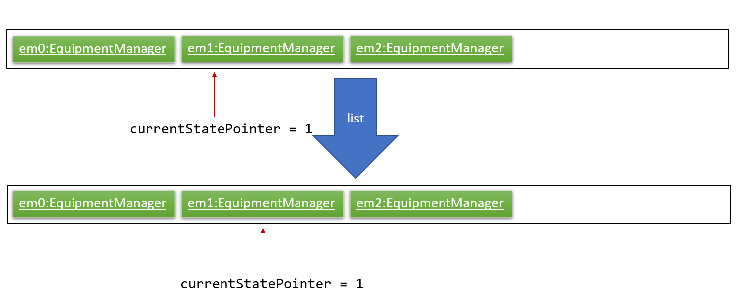
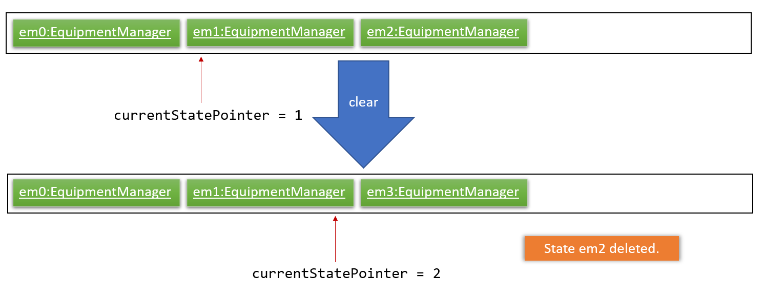
Step 6. The user executes clear, which calls Model#commitEquipmentManager(). Since the currentStatePointer is not pointing at the end of the equipmentManagerStateList, all Equipment Manager states after the currentStatePointer will be purged. We designed it this way because it no longer makes sense to redo the add n/Clementi CC … command. This is the behavior that most modern desktop applications follow.
The following activity diagram summarizes what happens when a user executes a new command:

4.9.2. Design Considerations
Aspect: How undo & redo executes
-
Alternative 1 (current choice): Saves the entire Equipment Manager.
-
Pros: Easy to implement.
-
Cons: May have performance issues in terms of memory usage.
-
-
Alternative 2: Individual command knows how to undo/redo by itself.
-
Pros: Will use less memory (e.g. for
delete-e, just save the equipment being deleted). -
Cons: We must ensure that the implementation of each individual command are correct.
-
Aspect: Data structure to support the undo/redo commands
-
Alternative 1 (current choice): Use a list to store the history of Equipment Manager states.
-
Pros: Easy for new Computer Science student undergraduates to understand, who are likely to be the new incoming developers of our project.
-
Cons: Logic is duplicated twice. For example, when a new command is executed, we must remember to update both
HistoryManagerandVersionedEquipmentManager.
-
-
Alternative 2: Use
HistoryManagerfor undo/redo-
Pros: We do not need to maintain a separate list, and just reuse what is already in the codebase.
-
Cons: Requires dealing with commands that have already been undone: We must remember to skip these commands. Violates Single Responsibility Principle and Separation of Concerns as
HistoryManagernow needs to do two different things.
-
4.10. Logging
We are using java.util.logging package for logging. The LogsCenter class is used to manage the logging levels and logging destinations.
-
The logging level can be controlled using the
logLevelsetting in the configuration file (See Section 4.11, “Configuration”) -
The
Loggerfor a class can be obtained usingLogsCenter.getLogger(Class)which will log messages according to the specified logging level -
Currently log messages are output through:
Consoleand to a.logfile.
Logging Levels
-
SEVERE: Critical problem detected which may possibly cause the termination of the application -
WARNING: Can continue, but with caution -
INFO: Information showing the noteworthy actions by the App -
FINE: Details that is not usually noteworthy but may be useful in debugging e.g. print the actual list instead of just its size
4.11. Configuration
Certain properties of the application can be controlled (e.g user prefs file location, logging level) through the configuration file (default: config.json).
5. Documentation
We use asciidoc for writing documentation.
| We chose asciidoc over Markdown because asciidoc, although a bit more complex than Markdown, provides more flexibility in formatting. |
5.1. Editing Documentation
See UsingGradle.adoc to learn how to render .adoc files locally to preview the end result of your edits.
Alternatively, you can download the AsciiDoc plugin for IntelliJ, which allows you to preview the changes you have made to your .adoc files in real-time.
5.2. Publishing Documentation
See UsingTravis.adoc to learn how to deploy GitHub Pages using Travis.
5.3. Converting Documentation to PDF format
We use Google Chrome for converting documentation to PDF format, as Chrome’s PDF engine preserves hyperlinks used in webpages.
Here are the steps to convert the project documentation files to PDF format.
-
Follow the instructions in UsingGradle.adoc to convert the AsciiDoc files in the
docs/directory to HTML format. -
Go to your generated HTML files in the
build/docsfolder, right click on them and selectOpen with→Google Chrome. -
Within Chrome, click on the
Printoption in Chrome’s menu. -
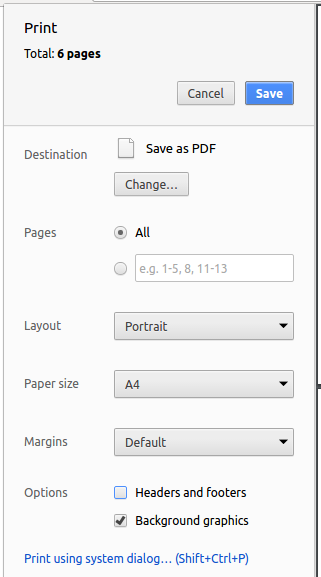
Set the destination to
Save as PDF, then clickSaveto save a copy of the file in PDF format. For best results, use the settings indicated in the screenshot below.
5.4. Site-wide Documentation Settings
The build.gradle file specifies some project-specific asciidoc attributes which affects how all documentation files within this project are rendered.
Attributes left unset in the build.gradle file will use their default value, if any.
|
| Attribute name | Description | Default value |
|---|---|---|
|
The name of the website. If set, the name will be displayed near the top of the page. |
not set |
|
URL to the site’s repository on GitHub. Setting this will add a "View on GitHub" link in the navigation bar. |
not set |
|
Define this attribute if the project is an official SE-EDU project. This will render the SE-EDU navigation bar at the top of the page, and add some SE-EDU-specific navigation items. |
not set |
5.5. Per-file Documentation Settings
Each .adoc file may also specify some file-specific asciidoc attributes which affects how the file is rendered.
All files under \docs\staticpages\ will be copied to final output documentation folders as well. You may put any static pages you want to public to \docs\staticpages.
Asciidoctor’s built-in attributes may be specified and used as well.
Attributes left unset in .adoc files will use their default value, if any.
|
| Attribute name | Description | Default value |
|---|---|---|
|
Site section that the document belongs to.
This will cause the associated item in the navigation bar to be highlighted.
One of: * Official SE-EDU projects only |
not set |
|
Set this attribute to remove the site navigation bar. |
not set |
5.6. Site Template
The files in docs/stylesheets are the CSS stylesheets of the site.
You can modify them to change some properties of the site’s design.
The files in docs/templates controls the rendering of .adoc files into HTML5.
These template files are written in a mixture of Ruby and Slim.
|
Modifying the template files in |
6. Testing
6.1. Running Tests
There are three ways to run tests.
| The most reliable way to run tests is the 3rd one. The first two methods might fail some GUI tests due to platform/resolution-specific idiosyncrasies. |
Method 1: Using IntelliJ JUnit test runner
-
To run all tests, right-click on the
src/test/javafolder and chooseRun 'All Tests' -
To run a subset of tests, you can right-click on a test package, test class, or a test and choose
Run 'ABC'
Method 2: Using Gradle
-
Open a console and run the command
gradlew clean allTests(Mac/Linux:./gradlew clean allTests)
| See UsingGradle.adoc for more info on how to run tests using Gradle. |
Method 3: Using Gradle (headless)
Thanks to the TestFX library we use, our GUI tests can be run in the headless mode. In the headless mode, GUI tests do not show up on the screen. That means the developer can do other things on the Computer while the tests are running.
To run tests in headless mode, open a console and run the command gradlew clean headless allTests (Mac/Linux: ./gradlew clean headless allTests)
6.2. Types of tests
We have two types of tests:
-
GUI Tests - These are tests involving the GUI. They include,
-
System Tests that test the entire App by simulating user actions on the GUI. These are in the
systemtestspackage. -
Unit tests that test the individual components. These are in
seedu.equipment.uipackage.
-
-
Non-GUI Tests - These are tests not involving the GUI. They include,
-
Unit tests targeting the lowest level methods/classes.
e.g.seedu.equipment.commons.StringUtilTest -
Integration tests that are checking the integration of multiple code units (those code units are assumed to be working).
e.g.seedu.equipment.storage.StorageManagerTest -
Hybrids of unit and integration tests. These test are checking multiple code units as well as how the are connected together.
e.g.seedu.equipment.logic.LogicManagerTest
-
6.3. Troubleshooting Testing
Problem: HelpWindowTest fails with a NullPointerException.
-
Reason: One of its dependencies,
HelpWindow.htmlinsrc/main/resources/docsis missing. -
Solution: Execute Gradle task
processResources.
7. Dev Ops
7.1. Build Automation
See UsingGradle.adoc to learn how to use Gradle for build automation.
7.2. Continuous Integration
We use Travis CI and AppVeyor to perform Continuous Integration on our projects. See UsingTravis.adoc and UsingAppVeyor.adoc for more details.
7.3. Coverage Reporting
We use Coveralls to track the code coverage of our projects. See UsingCoveralls.adoc for more details.
7.4. Documentation Previews
When a pull request has changes to asciidoc files, you can use Netlify to see a preview of how the HTML version of those asciidoc files will look like when the pull request is merged. See UsingNetlify.adoc for more details.
7.5. Making a Release
Here are the steps to create a new release.
-
Update the version number in
MainApp.java. -
Generate a JAR file using Gradle.
-
Tag the repo with the version number. e.g.
v0.1 -
Create a new release using GitHub and upload the JAR file you created.
7.6. Managing Dependencies
A project often depends on third-party libraries. For example, Address Book depends on the Jackson library for JSON parsing. Managing these dependencies can be automated using Gradle. For example, Gradle can download the dependencies automatically, which is better than these alternatives:
-
Include those libraries in the repo (this bloats the repo size)
-
Require developers to download those libraries manually (this creates extra work for developers)
Appendix A: Product Scope
Target user profile:
-
engineers who need to keep track of their preventive maintenance schedule
-
wants to plan the most efficient route to multiple locations
-
has a need to manage a significant number of contacts
-
prefer desktop apps over other types
-
can type fast
-
prefers typing over mouse input
-
is reasonably comfortable using CLI apps
Value proposition: help plan an efficient route for busy engineers to multiple locations and also carrying preventive maintenance on multiple equipment in a day.
Appendix B: User Stories
Priorities: High (must have) - * * *, Medium (nice to have) - * *, Low (unlikely to have) - *
Add, Edit, Delete, List (Basic CRUD commands)
| Priority | As a … | I want to … | So that I can… |
|---|---|---|---|
|
user |
create, update, and delete an equipment or its specific details |
keep the equipment information full and up-to-date. |
|
user |
create, update, and delete an worklist |
use worklist for tracking progress and tasks |
|
user |
have a worklist where I can store the equipments I am working on |
keep track of all the equipments that I am assigned to |
|
user |
view details of all equipment |
know how many equipment there are and what is the individual details of each equipment |
|
user |
want to know names of the clients |
so that i can get a clear view of my customers and their respective equipments |
Put, Remove
| Priority | As a … | I want to … | So that I can… |
|---|---|---|---|
|
user |
put an equipment into a work list |
arrange my equipments and put into a work list if I want to keep track of these equipments. |
|
user |
remove an equipment from a work list |
remove an equipment if I put it wrongly or I finished maintaining this equipment so I want to remove it from this work list. |
Filter
| Priority | As a … | I want to … | So that I can… |
|---|---|---|---|
|
user |
filter the list based on some conditions |
remove all irrelevant equipments showing on the list |
Sort
| Priority | As a … | I want to … | So that I can… |
|---|---|---|---|
|
user |
sort the list based on some fields |
view the list in a specific way |
Google Map And Route Planning
| Priority | As a … | I want to … | So that I can… |
|---|---|---|---|
|
user |
know the location where the equipment is at |
have a direct visual sense of the location of the equipment |
|
user |
have a visual representation of all equipments in the list |
have quick overview on information |
|
user |
plan efficient routes between multiple locations |
increase productivity, cut transportation costs, improve maintenance services |
Other commands
| Priority | As a … | I want to … | So that I can… |
|---|---|---|---|
|
new user |
learn how to use the application easily |
spend less time on learning and more on using it |
|
new user |
be able to understand the UI without much instruction |
spend my time on the program features |
|
user |
see my past commands |
keep track of what I have searched on |
|
user |
change command keywords |
use the words that I prefer |
|
user |
redo or undo my past commands |
correct any mistakes I have made |
|
user |
autocomplete my command queries |
get the information that I want faster |
Appendix C: Use Cases
For all use cases below, the System is the Equipment Manager and the Actor is the user, unless specified otherwise.
C.1. Use Case: Select Client
MSS
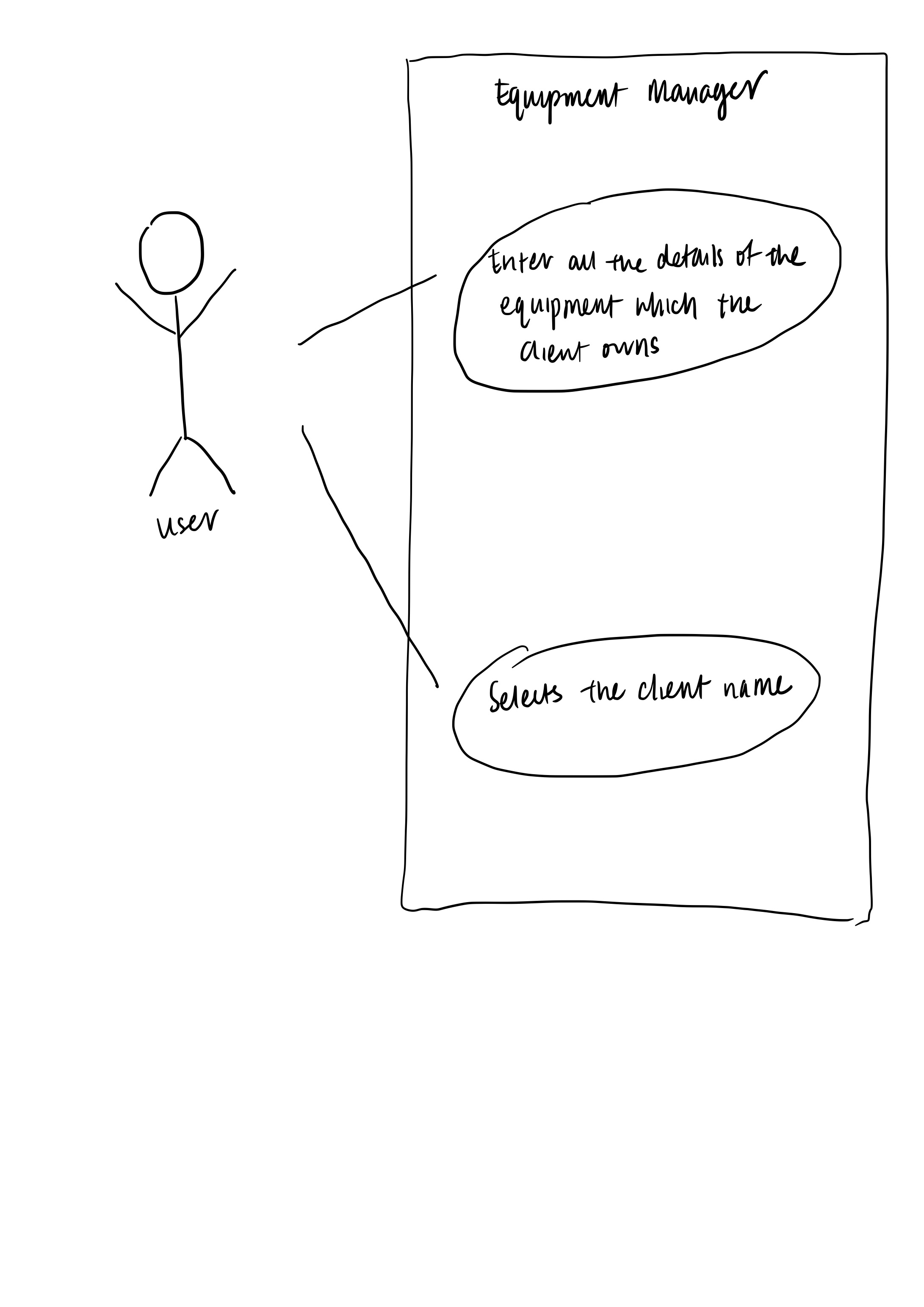
-
User selects the client name under Client details panel
-
The client name under Client details panel is selected
-
Equipment details panel shows a list of equipment that is owned by the client name
Use case ends.
Extensions
-
2a. The client name is listed in CLient details panel
Use case ends.
-
2b. The given index is empty.
Use case ends.
-
3a. The client does not own any equipment (as of now). Zero equipment listed.
Use case ends.
C.2. Use case: Delete equipment
MSS
-
User requests to list equipment
-
Equipment shows a list of equipment
-
User requests to delete a specific equipment in the list
-
Equipment Manager deletes the equipment
Use case ends.
Extensions
-
2a. The list is empty.
Use case ends.
-
3a. The given index is invalid.
-
3a1. Equipment Manager shows an error message.
Use case resumes at step 2.
-
Use case: Add worklist and put in equipments
MSS
-
User requests to list equipments
-
Equipment shows a list of equipments
-
User requests to create a new worklist
-
Equipment Manager create a worklist
-
User requests to put a new equipment into the worklist
-
Equipment Manager put the equipment into the worklist
Use case ends.
Extensions
-
3a. The parameters are invalid.
3a1. Equipment Manager shows an error message.
Use case resumes at step 3.
-
5a. The equipment list is empty.
User case ends.
-
5b. The given index is invalid.
-
5b1. Equipment Manager shows an error message.
Use case resumes at step 5.
-
Use case: Filter the equipments
MSS
-
User requests to list equipments
-
Equipment shows a list of equipments
-
User requests to filter the equipment list based on some parameters.
-
Equipment Manager filter the worklist and display to user
Use case ends.
Extensions
-
3a. The parameters are invalid.
-
3a1. Equipment Manager shows an error message.
Use case resumes at step 3.
-
-
3b. The equipment list is empty.
Use case ends.
Use case: Calculate route of equipments
MSS
-
User requests to list equipments
-
Equipment shows a list of equipments
-
User requests to calculate route of the equipment list with an origin address.
-
Equipment Manager calculate the route and display on the map
Use case ends.
Extensions
-
3a. The parameter address is invalid.
-
3a1. Equipment Manager shows an error message.
Use case resumes at step 3.
-
-
3b. The equipment list is empty.
Use case ends.
Appendix D: Non Functional Requirements
Non-functional requirements specify the constraints under which system is developed and operated.
-
Should work on any mainstream OS as long as it has Java
9or higher installed. -
Should be able to hold up to 1000 equipment without a noticeable sluggishness in performance for typical usage.
-
A user with above average typing speed for regular English text (i.e. not code, not system admin commands) should be able to accomplish most of the tasks faster using commands than using the mouse.
-
Should come with automated unit tests and be able to handle errors and exceptions.
-
Should be user-friendly for someone who have never used a CLI or software before to keep track of preventive maintenance schedule or route planning.
Appendix E: Glossary
If you do not understand a technical term used in this document, refer to Table 3, “Technical Terms” below.
| Term | Explanation |
|---|---|
Autocomplete |
Provides suggestions while you type into the field. |
Google Maps |
It is a online map service provided by Google. |
Mainstream Operating System (OS) |
Windows, Linux, Unix and OS-X are operating systems used widely in the world. |
User Interface (UI) |
Allows the user to interact with the application through inputs and outputs of data. |
Appendix F: Instructions for Manual Testing
Given below are instructions to test the app manually.
| These instructions only provide a starting point for testers to work on; testers are expected to do more exploratory testing. |
F.1. Launch and Shutdown
-
Initial launch
-
Download the jar file and copy into an empty folder
-
Double-click the jar file
Expected: Shows the GUI with a set of sample contacts. The window size may not be optimum.
-
-
Saving window preferences
-
Resize the window to an optimum size. Move the window to a different location. Close the window.
-
Re-launch the app by double-clicking the jar file.
Expected: The most recent window size and location is retained.
-
F.2. Equipment feature
-
Adding an equipment (identified by serial number)
-
Prerequisites: Add an equipment using the
add-e n/Clementi CC p/67762517 pm/01-05-2019 a/220 Clementi Ave 4, Singapore 129880 Rd s/X14DH9283command. Note that this equipment has serial number X14DH9283. -
Test case:
add-e n/Clementi CC p/67762517 pm/01-05-2019 a/220 Clementi Ave 4, Singapore 129880 Rd s/X14DH9283
Expected: Duplicated equipment serial number, this equipment already exists in the equipment manager. -
Test case:
add-e n/Clementi CCExpected: Invalid command format. Error details shown in message box. -
Other incorrect edit commands to try:
add(without giving the correct parameters)
-
-
Editing an equipment
-
Prerequisites: Starts off with an empty equipment list. To check, use
list-ecommand. If it is not empty, useclearcommand to clear all datas. -
Test case:
edit-e 1 n/Pending CC
Expected: The equipment index provided is invalid. -
Test case:
add-e n/Clementi CC p/67762517 pm/01-05-2019 a/220 Clementi Ave 4, Singapore 129880 Rd s/X14DH9283+edit-e 1 n/Pending CC p/65060900 a/8 Pending Rd, Singapore 678295
Expected: Equipment successfully modified. -
Test case:
edit-e 0 n/Pending CC
Expected: Invalid index given. -
Other incorrect edit commands to try:
edit,edit-e 1(without giving the parameters)
-
-
Deleting an equipment while all equipment are listed
-
Prerequisites: List all equipment using the
list-ecommand. Multiple equipment in the list. -
Test case:
delete-e 1
Expected: First equipment is deleted from the list. Details of the deleted equipment shown in the status message. Timestamp in the status bar is updated. -
Test case:
delete-e 0
Expected: No equipment is deleted. Error details shown in the status message. Status bar remains the same. -
Other incorrect delete commands to try:
delete,delete x(where x is larger than the list size) {give more}
Expected: Similar to previous.
-
F.3. Client feature
-
Selecting a client name
-
Prerequisites: App launch will provide list of equipment and client details displayed under Equipment details and Client details panel respectively.
-
Test case:
select-c 1
Expected: First client is selected from the client list. Equipments that are owned by this client will be listed under the Equipment details panel. -
Test case:
select 1
Expected: First equipment is selected from the equipment list, resulting in equipment details displayed in Equipment result page but this is not the correct command to select client from client list.
-
F.4. Sorting the equipment list
-
Sort the equipment list by specific fields
-
Prerequisites: Equipment list must have some entries in it.
-
Test case:
sort name
Expected: List is sorted by the name in alphabetical order. -
Test case:
sort date
Expected: List is sorted in ascending order by the the preventative maintenance date of the equipment. -
Test case:
sort phone
Expected: List is sorted in ascending order by the phone number of the client. -
Test case:
sort serial
Expected: List is sorted in ascending order by the serial number of the equipment. -
Test case:
sort
Expected: List will not be sorted. An error message will be displayed of what are the fields that are available.
-
F.5. Filtering the equipment list
-
Filter the equipment list to find specific equipment
-
Prerequisites: Equipment list must have some entries in it.
-
User requests to view equipment that matches certain criteria.
-
Equipment Manager displays equipment that matches the fields specified by the user.
-
Test case: User enters an invalid prefix for a field or does not specify any field.
Expected: An error message will be displayed to show the correct input.
-
F.6. Saving data
-
Dealing with missing/corrupted data files
-
Prerequisites: You must know where the data files are stored. By default, this will be at the data/ directory at the path of the jar file.
-
Test case: Delete the data directory and launch the app
Expected: A sample folder is present when the app launches (although it is not committed to storage until a persistent change is made).
-
Test case: Insert a non-json file/corrupted json file in the data directory and launch the app
Expected: The valid json files have folders with their corresponding names present. The non-json file/corrupted json file remains unaffected. { more test cases … }
-
F.7. Display the equipments
-
Display the equipments while there are some equipments in the list
-
Prerequisites: List all equipment using the
list-ecommand. Multiple equipments in the list. -
Test case:
display
Expected: Some red markers of equipments shown on the map
-
-
Display the equipments while no equipments in the list
-
Prerequisites: Clear all equipment using the
clearcommand. No equipment in the list. -
Test case:
display
Expected: No red markers of equipments shown on the map, but the map should still display.
-
F.8. Route the equipments
-
Route the equipments while there are some equipments in the list
-
Prerequisites: List all equipment using the
list-ecommand. Multiple equipments in the list. -
Test case:
route School of Computing, NUS, Singapore
Expected: Route of some equipments with valid and concise addresses will be shown and route will be calculated. -
Test case:
route
Expected: Browser panel do not change. Error messages shown.
-
-
Display the equipments while no equipments in the list
-
Prerequisites: Clear all equipment using the
clearcommand. No equipment in the list. -
Test case:
route School of Computing, NUS, Singapore
Expected: Only a marker shwon on the map, no routes calculated. Map will still display.
-